


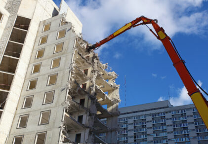
A hydraulic hammer can run within its rated working pressure all day and still wear out a standard push-to-connect quick coupler well ahead of its expected service life. The damage comes from repeated pressure spikes, not the steady pressure the circuit is designed around. Each spike loads the coupler’s locking and valve components, and in a hammer, breaker or drilling circuit those spikes continue for the entire duty cycle. Stucchi’s thread-to-connect flat-face couplings are designed for that duty. Select Stucchi connect-under-pressure couplers are designed to connect under residual pressure.
This guide explains what makes a circuit high impulse, how impulse damage shows up at the connection, and which factors decide whether a coupler will survive it. It also maps Stucchi’s thread-to-connect series to these circuits and covers ISO 16028 interchange and the field practices that extend coupling life.
What Makes a Hydraulic Circuit High Impulse?
A high-impulse circuit is one where pressure rises and falls sharply and repeatedly during normal operation instead of holding near a steady value. The peaks are brief, but they recur thousands of times per shift and often exceed the circuit’s nominal operating pressure.
Four conditions create these impulses:
- Percussive tools. Hammers and breakers cycle an internal piston at high frequency, sending pressure pulsations back through the supply and return lines.
- Shock loading. Shears, crushers, and drilling heads stall or suddenly break through material, so flow stops or reverses instantly.
- Valve shifts and load reversals. Fast directional changes and actuator reversals send pressure surges through the connected circuit.
- Relief valve response time. A relief valve limits sustained pressure, but a fast spike can pass through the circuit before the valve fully opens.
The quick coupler sits directly in that flow path. Every impulse acts on its valves, seals, and locking mechanism, which makes the connection a common place for impulse damage to appear first.
Why Working Pressure Ratings Don’t Tell the Whole Story
A coupler’s working pressure rating describes the continuous pressure it can handle in normal operation. It does not describe how the coupler behaves under hundreds of thousands of rapid pressure cycles. A coupler can be correctly rated for a circuit’s nominal pressure and still fail early, because the peaks, not the average, do the damage.
Those peaks are often invisible. Dampened gauges and nameplate values show steady-state pressure, while short spikes usually take a high-frequency pressure transducer or data logger to capture. A circuit can look comfortably inside its ratings while the connection sees much higher peak loads.
The damage is also cumulative. Each cycle loads the locking elements, valve seats and seals, and the wear compounds over time. A coupler rated just above nominal system pressure is the most exposed, because its margin disappears during every peak. Stucchi’s Understanding Working and Burst Pressure Ratings guide explains how these ratings are defined and why the connected-pair rating matters.
For a high-impulse circuit, the specification should include:
- The measured peak pressure the circuit sees, not the relief setting
- The expected cycle frequency and duty cycle
- The coupler’s connected-pair working pressure
- The coupler manufacturer’s impulse test data
Common High-Impulse Applications
High-impulse conditions concentrate in attachments that strike, cut, crush or drill. The auxiliary circuit feeding these tools carries their pressure pulsations straight to the quick coupler.
| Application | Where the impulse comes from | What it means at the coupler |
|---|---|---|
| Hydraulic hammers and breakers | A piston striking at high frequency for the whole duty cycle | Constant pulsation, plus frequent changeovers on excavators and skid steers |
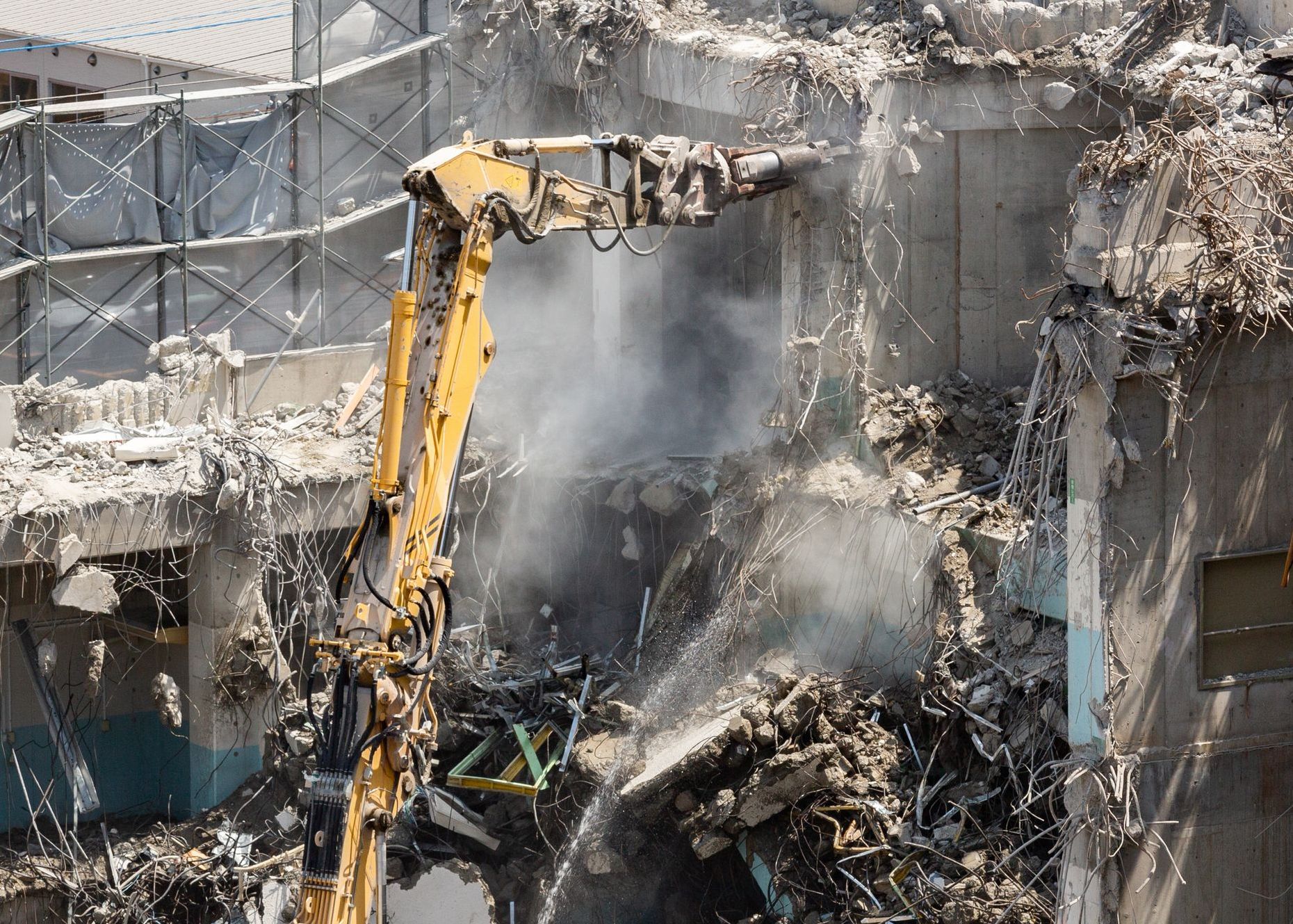
| Demolition shears, crushers and pulverizers | Shock loads when concrete or steel suddenly gives way | Long hose runs, vibration and frequent hammer-to-crusher tool changes |
| Rock drills and drilling heads | Impulse loading at high working pressure | Hose movement, and junction points that must stay sealed under vibration |
| Vibratory compactors and tampers | Continuous vibratory loading | Vibration transmitted back through the hoses to the connection |
| Excavator thumbs and grapples | Repeated shock as they clamp and release heavy loads | A shock load at the connection on every cycle |
| Forestry mulchers and land-clearing heads | Rotor strikes on wood, rock or debris, at high flow | Heat that raises residual pressure in the lines after shutdown |
Stucchi’s bridge demolition case study shows how a contractor used VEPHDL heavy-duty, locking threaded couplers to get through two days of heavy hammering and attachment changeovers on a 56-hour Denver bridge demolition.
Failure Symptoms in High-Impulse Connections
Impulse damage at the coupler tends to progress in a recognizable sequence. Catching the first sign prevents the leaks, downtime, and safety exposure that follow.
Brinelling: The First Sign
Brinelling is the permanent indentation of a hardened surface under repeated impact loading. In a ball-locking coupler, each pressure impulse pushes the halves apart slightly and presses the locking balls into the groove of the male nipple. Over many cycles, the balls leave dents in the groove and sleeve. A ring of evenly spaced indentations around the locking groove is the clearest sign. Stucchi’s article Why Quick Couplers Fail on Hydraulic Breakers explains how to diagnose it.
What Follows Brinelling
- Axial play and leakage. Dented locking surfaces let the halves move against each other. That movement wears the seals and sealing faces, and the connection starts to weep and collect grit.
- Valve damage. Internal valves and seals take the full force of surge flow and pressure reversal. Watch for internal leakage, valves that hang partly open or closed, restricted flow or heat at the coupler.
- Hard connections or unintended release. Worn locking parts make couplers harder to connect and disconnect, or let them separate under load. A release under pressure creates a fluid-injection hazard and an immediate spill.
- Repeat replacements. Replacing the same coupler on the same attachment repeatedly means the connection doesn’t match the circuit. Stucchi’s article Before You Replace a Hydraulic Coupler, Review the Application covers that review.
Selection Factors for High-Impulse Quick Couplings
The right coupler for a high-impulse circuit is chosen from the operating conditions, not the catalog. Each factor below changes which connection will hold up.
Pressure Spikes and Impulse Data
Start with the measured peak pressure, not the relief setting. Compare that peak against the coupler’s connected-pair working pressure and its impulse test data, and leave margin for transients the measurement may have missed.
Locking Method
The locking method decides how impulse loads are carried. A ball-locking coupler concentrates the load on a few small contact points, which is where brinelling starts. A thread-to-connect coupler spreads the load around the full thread engagement and holds the halves together without the axial play that drives brinelling.
Flow and Pressure Drop
Hammers and mulchers often run at high flow. An undersized coupler body for the actual flow adds pressure drop and heat, and heat raises residual pressure after the machine stops. Check the pressure drop curve at the attachment’s real operating flow. Stucchi’s guide to Understanding Hydraulic Pressure Drop explains how to read those curves.
Residual Pressure
High-impulse attachments are often stored hot, in the sun or with load on their cylinders, and all three trap pressure in the lines. Find out whether residual pressure appears on one side of the connection or both. That answer separates one-side connect-under-pressure couplers from thread-to-connect designs that connect with pressure on both halves. Stucchi’s Connect Under Pressure guide explains both approaches.
Vibration, Torsion and Hose Rotation
Percussive tools shake the hoses continuously, and boom movement twists them. Under those conditions, a threaded sleeve can work loose unless it is positively locked, so a locking or auto-locking sleeve is the safer choice. Where hoses rotate in service, a live swivel at the coupling keeps that rotation from working against the connection.
Connection Frequency
Attachments swapped several times a shift need a connection operators can make quickly and correctly every time. Look for wrench flats, connection indicators, and a design that cannot be left half-connected.
Contamination Exposure
Demolition, quarry and forestry sites expose couplers to dust, slurry and debris at every change. Flat-face mating surfaces wipe clean before connection and leave fewer cavities for dirt to collect. Stucchi’s Contamination Control Guide explains how the connection point affects overall system cleanliness.
Stucchi Coupling Series for High-Impulse Circuits
Stucchi’s thread-to-connect couplings are the primary solution for high-impulse circuits. The thread-to-connect design eliminates the premature wear and brinelling associated with ball-locking designs, and each series is designed to connect under residual pressure on both sides of the circuit. The family runs from the VEP baseline through heavy-duty, locking and auto-locking versions to the VT17-ZN RoT-lock. The A-HD Series meets a different need: ISO 16028 circuits where residual pressure, not severe impulse, is the main problem.
| Series | Connection type | Body sizes | Working pressure | Max residual pressure at connection | Key features | Typical fit |
|---|---|---|---|---|---|---|
| VEP | Thread-to-connect flat face | 1/4″ to 2″ | 35–60 MPa / 5,075–8,700 psi range | 25 MPa / 3,625 psi | Patented internal valve; yellow O-ring indicator; NPT, SAE, BSP, ORFS ports; interchanges with VEPHD and VEPHDL | Excavator auxiliary lines for hammers, thumbs, grapples and compactors; cranes, drilling machines and oil field junction points |
| VEPHD | Thread-to-connect flat face, heavy duty | 3/4″ to 1 1/2″ | 40–55 MPa / 5,800–7,975 psi range | 25 MPa / 3,625 psi | Higher-grade steel; full QPQ body; larger mating areas; wrench flats on the male; NPT, SAE, flange ports; interchanges with VEP and VEPHDL | High-impulse mobile circuits; excavator hammers, compactors, tampers and demolition tools |
| VEPHDL | Thread-to-connect flat face, heavy duty with locking pin | 3/4″ to 1 1/4″ | 5,800–7,975 psi range | 25 MPa / 3,625 psi | Locking female with visual connection indicator; NPT, SAE, Code 62 flange ports; interchanges with VEPHD and VEP | High-pressure, high-impulse circuits with vibration and torsion where a failsafe connection is critical |
| VP | Thread-to-connect flat face with auto-lock sleeve | 1/4″ to 1 1/2″ | 40–60 MPa / 5,800–8,700 psi range | 25 MPa / 3,625 psi | Safety auto-lock sleeve for positive secondary retention; NPT, SAE, BSP, flange ports | Construction equipment with high pressure or residual-pressure problems; excavator hammers, thumbs and grapples |
| VT RoT-lock | Screw-to-connect flat face with automatic locking sleeve | 1″ | 500 bar / 7,250 psi operating | Connection allowed with residual pressure on both sides | Integrated live swivel on the male; axial bearing; optimized thread for fewer turns to connect; NPT ports | Severe pressure impulses with high vibration and hose rotation, or where a redundant locking system is required |
| A-HD | ISO 16028 push-to-connect flat face | 3/8″ to 1/2″ | 4,785–5,075 psi max operating, coupled | 1,595 psi | Connects by hand under residual pressure; black ID ring; NPT, SAE, JIC, ORFS, BSP ports | Mobile attachments where thermal expansion traps pressure and ISO 16028 interchange must be kept |
Ratings vary by size and port configuration. Confirm the value for the exact part number on the product page or with the Technical Help Desk before specifying.
How to Choose Between the Series
- Choose VEP as the baseline thread-to-connect coupling, with the widest size range.
- Choose VEPHD for severe duty cycles. It keeps VEP interchange and adds higher-grade steel and full QPQ plating.
- Choose VEPHDL where vibration and torsion could back off a threaded sleeve. Its locking female and visual indicator confirm a complete connection.
- Choose VP for positive secondary retention from a safety auto-lock sleeve, across sizes from 1/4″ to 1 1/2″.
- Choose the VT RoT-lock where hoses rotate in service. Its live swivel and axial bearing let the hose turn without loosening the connection, and its automatic locking sleeve adds redundant retention.
- Choose A-HD where ISO 16028 interchange must be kept and residual pressure, not severe impulse, is the issue.
Spillage and Contamination at the Connection
Stucchi flat-face couplers provide zero-spill performance with virtually zero fluid loss per disconnect. The flat faces are fast and easy to wipe clean, supporting contamination control at the connection point.
That matters more in impulse service. Hammers and demolition tools change often, on sites full of dust, slurry, and concrete fines. Every changeover is a chance for dirt to enter the circuit, and a worn connection that weeps oil collects grit between changeovers too.
Stucchi publishes spillage per disconnect on its product pages. Values vary by body size, so confirm the figure for the exact part number.
Stucchi’s Zero-Spill Hydraulic Connections hub covers the full contamination-control program.
ISO 16028 Interchange Considerations
Stucchi’s thread-to-connect couplings and ISO 16028 push-to-connect couplings use different interfaces and are not interchangeable. Moving a high-impulse circuit from ISO 16028 to a thread-to-connect series is a conversion of both halves, not a part swap.
ISO 16028 defines the dimensions and performance requirements for flat-face push-to-connect couplings, and many mixed fleets and rental attachments are built around it. The interface dimensions of the Stucchi flat-face design became the basis for ISO 16028, adopted in 1999. Interchangeability across brands is the standard’s main advantage.
When to Convert to Thread-to-Connect
Conversion makes sense on a dedicated hammer or demolition circuit, where the same tool stays with the same carrier or fleet and cross-brand interchange matters less. Plan it as a group change:
- List every machine and attachment that shares the circuit.
- Confirm what is installed today with Stucchi’s Physical ID Charts.
- Convert both halves across the whole group, because a carrier fitted with thread-to-connect couplers will not accept attachments still fitted with ISO 16028 halves.
Stucchi’s Hydraulic Interchangeability for Mixed Fleets resource covers fleet-wide planning.
When to Stay Within ISO 16028
Where attachments move between machines or brands, keeping ISO 16028 interchangeability may outweigh converting. The decision then shifts to the coupler’s construction, pressure rating, impulse data and connect-under-pressure capability within that standard. The standard defines the interface, not impulse performance, so two ISO 16028 couplers can behave very differently on the same breaker circuit.
Cleaning, Inspection and Connection Practices
The right coupler lasts longest when it is connected correctly and inspected on a schedule. These practices apply to thread-to-connect and flat-face couplings in high-impulse service.
Before Every Connection
- Shut down the carrier and relieve system pressure following the machine manufacturer’s procedure. Never connect or disconnect with the pump delivering pressure to the line.
- Remove dust caps and plugs, and wipe both mating faces clean.
- On VEP-family couplers, pull the female’s connection sleeve forward, align the halves, and thread them together by turning the sleeve. Keep the halves aligned throughout, and do not push to connect.
- With high residual pressure in the circuit, a wrench may be needed for the final part of the connection. Use the wrench flats provided rather than striking the coupler.
- On locking versions, confirm the lock is fully engaged before running the tool: the visual indicator on VEPHDL, or the auto-locking sleeve on VP and VT17-ZN RoT-lock.
After Disconnection
- Install dust caps and plugs on both halves right away.
- Store attachments out of direct sun where possible to limit thermal pressure build-up.
- Rest attachments on the ground so cylinders don’t hold load in the lines.
Routine Inspection
- Check the mating faces for nicks, scoring or pitting that could cut seals.
- Look for dents around the locking grooves of any ball-locking couplers still in the circuit.
- Check for weeping or oil film at the connection after operation.
- Note any change in connection effort, heat at the coupler or slower attachment response, which can signal valve damage or rising pressure drop.
- Replace damaged seals with the manufacturer’s repair kit, and replace the coupler when body or locking surfaces are damaged.
Stucchi’s Standard Operating Procedures for Zero-Spill article covers connection discipline in more detail. For lockout, stored-energy and safe-disconnection practice, see the Hydraulic Safety & Reliability hub. Always follow the machine manufacturer’s manual and your site’s stored-energy procedures.
What the Right Connection Changes
Matching the coupling to the impulse duty changes the cost of running the attachment, not just the life of one part. The gains show up in four places:
- Fewer repeat replacements. A connection that does not brinell ends the cycle of replacing the same coupler on the same attachment.
- Faster changeovers. Couplings that connect under residual pressure remove the bleeding, forcing, and extra trips to the cab that slow tool changes.
- Cleaner oil and cleaner sites. A sound flat-face connection does not weep, so less oil reaches the ground and less grit reaches the circuit.
- Lower operator exposure. Fewer forced connections and fewer worn locks mean fewer chances for fluid injection, hot-oil spray or an unintended release.
Frequently Asked Questions
What is a high-impulse hydraulic circuit?
A high-impulse circuit experiences rapid, repeated pressure spikes during normal operation. Hydraulic hammers, breakers, demolition shears and crushers, rock drills and compactors are common examples.
What is brinelling in a hydraulic quick coupler?
Brinelling is permanent denting of hardened surfaces caused by repeated impact loading. In ball-locking couplers, pressure impulses drive the locking balls into the male nipple’s groove until they leave indentations, which creates play, wear and eventually leakage.
Why do thread-to-connect couplers resist brinelling?
The threads carry the load across the full engagement instead of at a few ball contact points, and they hold the halves together without axial play. Stucchi’s VEP, VEPHD, VEPHDL, VP, and VT RoT-lock series all use a threaded connection for high-impulse, high-residual-pressure circuits.
Is a coupler’s working pressure rating enough for a hammer circuit?
No. Working pressure describes continuous operation. Before specifying a coupler for a hammer circuit, compare the measured peak pressure, the cycle frequency, and the coupler’s impulse test data as well.
Are VEP couplers interchangeable with ISO 16028 flat-face couplers?
No. VEP, VEPHD and VEPHDL interchange with each other, but not with ISO 16028 push-to-connect couplers. VP and VT RoT-lock are also thread-to-connect designs outside ISO 16028. Converting a circuit means changing both the machine and attachment halves.
Can these couplers connect with pressure trapped in the lines?
Yes. Select Stucchi connect-under-pressure couplers are designed to connect under residual pressure. VEP, VEPHD, VEPHDL and VP are rated for connection with up to 25 MPa / 3,625 psi of residual pressure, and the VT RoT-lock allows connection with residual pressure on both sides. The A-HD Series connects by hand with up to 1,595 psi of residual pressure on ISO 16028 circuits. The correct series depends on the application, pressure, flow, connection method, and duty cycle.
How do Stucchi flat-face couplers help reduce fluid loss and contamination?
Stucchi flat-face couplers provide zero-spill performance with virtually zero fluid loss per disconnect. The flat faces are fast and easy to wipe clean, supporting contamination control at the connection point.
Review Your High-Impulse Circuit with Stucchi’s Technical Help Desk
High-impulse coupler selection depends on details that rarely appear on a nameplate: measured peak pressure, actual attachment flow, residual pressure on each side of the connection, and how often the tool is changed. Stucchi looks beyond the part number to understand the application and solve the operating problem. Stucchi USA provides direct North American engineering support with sizing guidance and CAD models.
Send your circuit details to Stucchi’s Technical Help Desk or through the contact form. Include the attachment type, carrier model, operating flow and pressure, and any coupler failures you have seen. The Technical Help Desk supports product identification, application review and series selection.