VLS SERIES

The VLS Series Heavy-Duty Screw Coupler is a durable product using heavy duty poppet style valves for the sealing mechanism and threads as the mechanical connection. The VLS series couplings feature a particularly rugged design, making them particularly well suited for heavy-duty service conditions, including construction equipment used in extreme off-highway conditions.

Speak to a Specialist:
847-956-9720 or Via Email

Related Industries

  • Coiled tubing

  • Die Casting

  • Mobile

  • Snow & Ice

Description

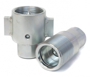
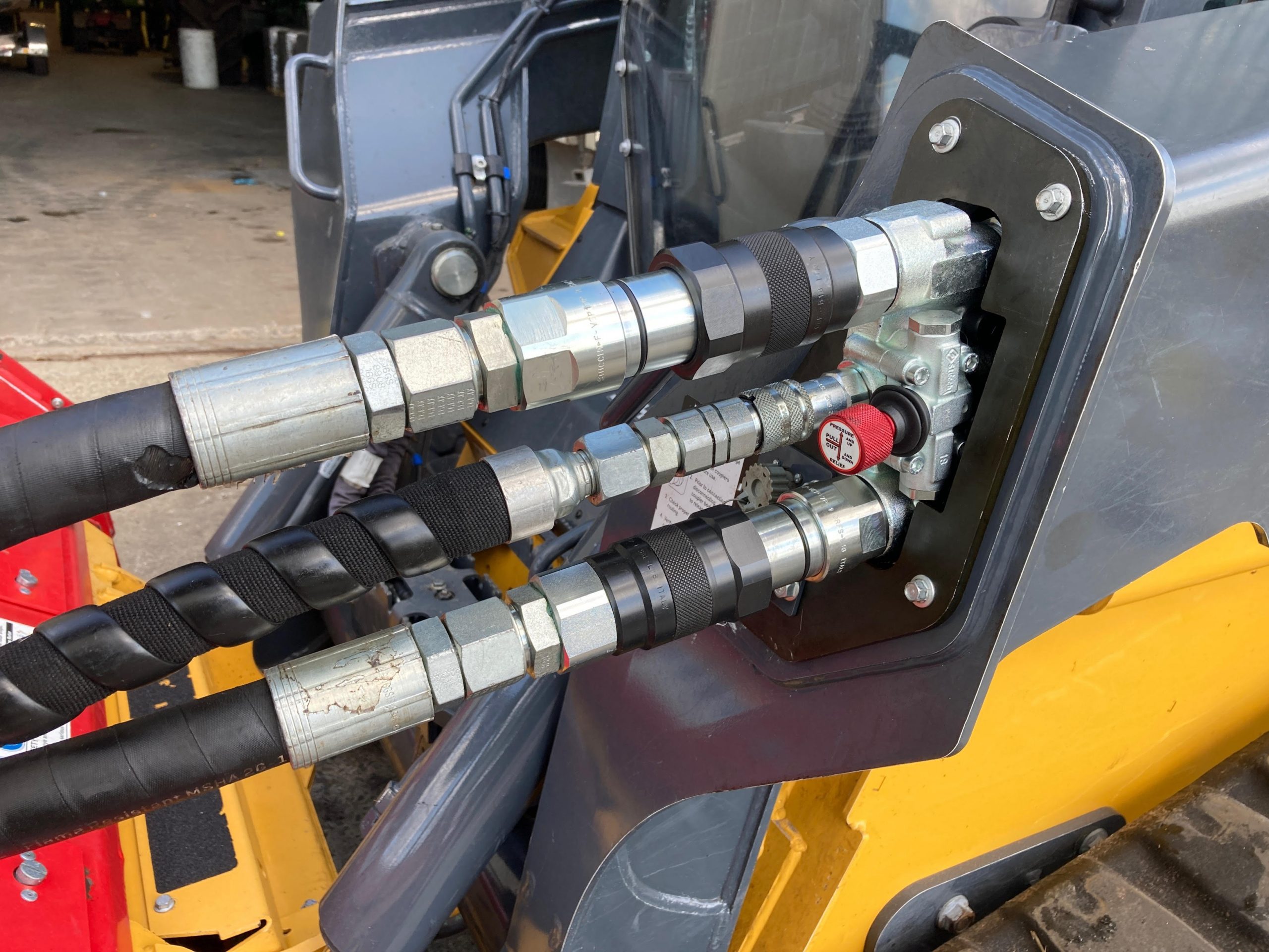
Heavy Duty Screw Coupler

FEATURES
  • Size range: 1/2” thru 1”
  • Port options: BSP, DIN
  • Screw-on system interchangeable with German market couplings
  • Internal components designed to reduce turbulence and handle impulse applications
  • Zinc plated steel coupling body with zinc plated hardened steel nipple
  • Nitrile seals and Teflon anti-extrusion rings
  • Available in two sizes: 1/2 and 1 inch
APPLICATIONS
  • Particularly well suited for heavy-duty service conditions
  • Off-highway applications, especially in construction equipment under extreme conditions
  • Wherever turbulence must be reduced and impulses must be managed

Pressure Drop

vls pressure drop

Performance

MAX. OPERATING PRESSURE BURST PRESSURE
COUPLED MALE FEMALE COUPLED MALE FEMALE
DESCRIPTION MPa psi MPa psi MPa psi MPa psi MPa psi MPa psi
VLS12 46.5 6743 46.5 6743 46.5 6743 200 29000 130 18850 170 24650
VLS100 46.5 6743 46.5 6743 46.5 6743 140 20300 140 20300 140 20300
SIZE RATED FLOW MAX. FLOWSUGGESTED CONNECTTORQUE* DISCONNECTTORQUE* SPILLAGE**
DESCRIPTION inch L/min GPM L/min GPM NM LBF FT NM LBF FT ml
VLS12 1/2 45 11.93 90 23.85 3.2 2.36 3.2 2.36 2.5
VLS100 1 100 26.50 200 53.00 1.3 0.96 0.6 0.44 15

* Connect torque and disconnect torque without residual pressure. Torque will increase with residual pressure.
** Spillage is an indicative value of the fluid loss per couple-uncouple cycle without residual pressure.

Size Diagram

vls size diagram

DESCRIPTION BODYSIZE ISO A E UNIT HEX B D F G M N HEX P HEX Q T
VLS 12 BSP 1/2 12,5 G 1/2′ 35X2 SP mm 27 50,3 62 92.6 35.5 45 41 32 29.8
inch 1.06 1.98 2.44 3.65 1.40 1.77 1.61 1.26 1.17
VLS 100 BSP 1 25 G 1′ 54X3 SP mm 41 66.9 101.5 143 50 72 65 46 54
inch 1.61 2.63 4.00 5.63 1.97 2.83 2.56 1.81 2.13
WEIGHT
DESCRIPTION UNIT MALE FEMALE
VLS 12 BSP kg 0.245 0.315
lbs 0.111 0.143
VLS 100 BSP kg 0.92 0.88
lbs 0.417 0.399
DESCRIPTION BODYSIZE ISO A E UNIT HEX B D F G M N HEX P HEX Q T
VLS 12
M22X1.5 ISO
1/2 12.5 M22X1.5 35X2 SP mm 27 50.3 62 92.6 35.5 45 41 32 29.8
inch 1.06 1.98 2.44 3.65 1.40 1.77 1.61 1.26 1.17
VLS 100
M30X1.5 ISO
1 25 M30X1.5 54X3 SP mm 41 66.9 101.5 143 50 72 65 46 54
inch 1.61 2.63 4.00 5.63 1.97 2.83 2.56 1.81 2.13
WEIGHT
DESCRIPTION UNIT MALE FEMALE
VLS 12 M22X1.5 ISO kg 0.24 0.305
lbs 0.109 0.138
VLS 100 M30X1.5 ISO kg 0.94 0.9
lbs 0.426 0.408

VLS BSP and DIN Thread

PART BODYSIZE THREADTYPE THREADSIZE PORTSERIES PORTTHREAD ORDER CODE DESCRIPTION
VLS BSP THREAD
COUPLER 1/2 BSP 1/2 FEMALE 1/2-14 809900004 F. VLS 12 BSP
NIPPLE 1/2 BSP 1/2 FEMALE 1/2-14 809900005 M. VLS 12 BSP
COUPLER 1 BSP 1 FEMALE 1-11 809900008 F. VLS 100 BSP
NIPPLE 1 BSP 1 FEMALE 1-11 809900009 M. VLS 100 BSP
VLS DIN THREAD
COUPLER 1/2 DIN M 22X1.5 FEMALE 809912004 F. VLS M22X1.5 ISO
NIPPLE 1/2 DIN M 22X1.5 FEMALE 809912005 M. VLS M22X1.5 ISO
COUPLER 1 DIN M 30X1.5 FEMALE 809912008 F. VLS 100 M30X1.5 ISO
NIPPLE 1 DIN M 30X1.5 FEMALE 809912009 M. VLS 100 M30X1.5 ISO

VLS Series Accessories Aluminum Screw Caps

ORDER CODE
DESCRIPTION PLUG FOR FEMALE CAP FOR MALE
VLS12 814906022 814906023
VLS100 814906024 814906025

Additional information

Body Size

,

Material

Port Options

,

Port Size

,

Valve Style

Working Pressure